2005-2009 Kawasaki Brute Force 650/KVF 650 4x4 Service Manual, Page 122Get this manual
5-14 ENGINE TOP END Rocker Case
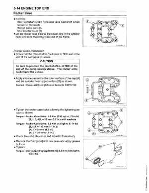
RemoveRear Camshaft Chain Tensioner (see Camshaft Chain Tensioner Removal) Rocker Case Bolts [A] Rear Rocker Case [B) Lift the rocker case clear of the dowel pins in the cylinder head and slide the rocker case out of the frame
HE10 03 BS1
Rocker Case Installation
Check that the crankshaft is positioned at TOC and at the end of the compression stroke
CAUTION
Be sure to position the crankshaft is at TOe of the end of the compression strokeThe rocker arms could bend the valves Apply silicone sealant to the outer surface of the cap [A] and the cylinder head upper surface [B) as shown SealantKawasaki Bond (Silicone Sealant): 56019-120