2005-2009 Kawasaki Brute Force 650/KVF 650 4x4 Service Manual, Page 121Get this manual
ENGINE TOP END 5-13 Rocker Case
Rocker Case Removal
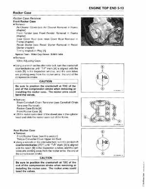
Front Rocker Case Remove: Air Cleaner Cover (see Air Cleaner Removal in Frame chapter) Front Fender (see Front Fender Removal in Frame chapter) Inner Cover Rear (see Inner Cover Rear Removal in Frame chapter) Recoil Starter (see Recoil Starter Removal in Recoil Starter chapter) Timing Inspection Plug [A]
Special ToolFiller Cap Driver: 57001-1454
Remove: Valve Adjusting Caps Using wrench on the alternator bolt, turn the crankshaft counterclockwise until "T-F" mark [A] is aligned with the notch [B] in the inspection window, and the cam lobes are pointing away from the rocker arms: the end of the compression stroke
CAUTION
Be sure to position the crankshaft at TOC of the end of the compression stroke when removing or installing the rocker caseThe rocker arms could bend the valves Remove: Front Camshaft Chain Tensioner (see Camshaft Chain Tensioner Removal) Rocker Case Bolts [A] Front Rocker Case [B] Lift the rocker case clear of the dowel pins in the cylinder head and slide the rocker case out of the frame