2004 Kawasaki KFX 700 V Force Factory Service Manual, Page 176Get this manual
CONVERTER SYSTEM 6-25 Driven Pulley
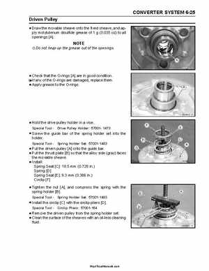
sheave onto the and Draw the movabledisulfide grease offixed sheave,oz) toapply molybdenum (0.035 all openings [A]
Do not heap up the grease out of the openings
that Checkof thethe O-rings [A] are in good conditionIf any O-rings are damaged, replace themApply grease to the O-rings
Hold the drive pulley holder in vise
Screw the guide bar of the spring holder set into the holderpulley [A] onto Put the driven plate [B] so thatthe guide bar(gray) faces Put the thrust the alloy side the movable sheave Install: Seat [C]: 18.5 mm (0.728 in Spring Spring [D] Spring Seat [E]: 9.3 mm (0.366 in Circlip [F] the Tightenholdernut [A], and compress the spring with the spring [B]Special ToolSpring Holder Set: 57001-1483