2004-2006 Kawasaki Prairie 700 4x4, KVF 700 4x4 service manual, Page 175Get this manual
6-22 CONVERTER SYSTEM Drive Pulley
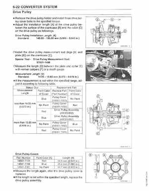
Remove the drive pu lley holder and install three drive pulley cover bolts to the specified torque Adjust the installation length [A] of the drive pu lley between the surface of the crankcase [8] and the collar [C] on the drive pulley as followi ngsDrive Pulley Ins, allation Length [A] Standard: 149.85150.95 mm (5.9005943 in
Olnstall the drive pulley measurement tool (legs [AJ and plate [8J) on the crankcase [elSpecial lioolDrive Pulley Measurement Tool: 57001 -1 498
OMeasure the length (0] between the plate and col lar [E] with vernier calipers [F) or depth gaugeMeasulrement Length [DJ Standard14.55
15.65 mm (05730.616 in
If the measurement is not withi the specified range, adjust it accord ing to following tableStatus Quo Replacement Part Measurement Paint Color Replace Part Pa int Color Length of Cover (Part Number) of Cover Pulley Cover Blue No Paint (14041-1161less than 14.55 mm Pulley Cover No Pa int Red (0.573 in (1404 1-1159) Drive Pulley Assembly Red (49093-002) Drive Pulley Assembly Bl ue (49093-002) more than 15.65 mm Pulley Cover No Paint Blue (0.616 in (14041-1160) Pulley Cover No Paint Red (14041-1161)