2004 John Deer Buck Utility ATV 500, 500EX and 500EXT Service Manual, Page 177Get this manual
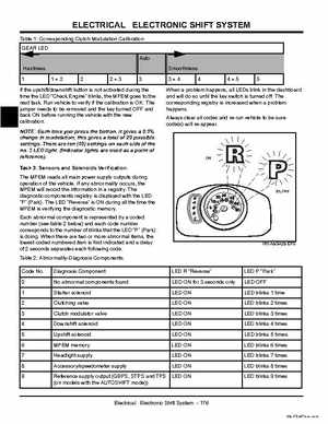
Table 1: Corresponding Clutch Modulation Calibration GEAR LED Auto Hardness 1+2 2+3 Smoothness 3+4 4+5 5
If the upshiftdownshift button is not activated during the time the LED "Check Engine" blinks, the MPEM goes to the next taskRun vehicle to verify if the calibration is OKThe jumper needs to be removed and the key turned OFF and back ON before running the vehicle with the new calibration
When problem happens, all LEDs blink in the dashboard and will do so until the key switch is turned offThe corresponding registry is increased when problem happensAlways clear all codes and re-run vehicle to be sure code(s) will re-appear
The MPEM reads all main power supply outputs during operation of the vehicleIf any abnormality occurs, the MPEM will record the information in registryThe diagnostic components registry is displayed with the LED "P" (Park)The LED "Reverse" is ON during all the time the MPEM is verifying the diagnostic memoryEach abnormal component is represented by coded number (see table below) and each code number corresponds to the number of blinks that the LED "P" (Park) is doingWhen there are two or more abnormal items, the lowest coded numbered item is first indicated and delay of seconds separates each following codeTable 2: Abnormality-Diagnosis Components Code No0 Diagnosis Component No abnormal components found Starter solenoid Clutching valve Clutch modulator valve Downshift solenoid Upshift solenoid MPEM memory Headlight supply Accessoryspeedometer supply Reference supply output (GBPS, STPS and TPS (on models with the AUTOSHIFT mode)) LED "Reverse" LED ON for seconds only LED ON LED ON LED ON LED ON LED ON LED ON LED ON LED ON LED ON LED "Park" LED OFF LED blinks time LED blinks times LED blinks times LED blinks times LED blinks times LED blinks times LED blinks times LED blinks times LED blinks times