2004 John Deer Buck Utility ATV 500, 500EX and 500EXT Service Manual, Page 174Get this manual
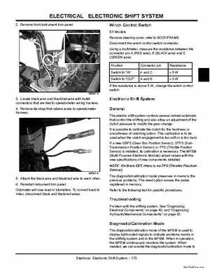
2Remove front instrument trim panelEX Models Remove steering cover, refer to BODYFRAMEDisconnect the winch control switch connectorUsing multimeter, measure the resistance between the connector pin (RED wire), (BLACK wire) and (GREEN wire)Position Switch to "IN" Switch to "OUT" Connector pin and and Resistance 5W 5W
If the resistance is above W, change the winch control switch63047-2
3Locate black wire and blackred wire with bullet connectors that are tied to speedometer wiring harness4Remove tie strap that retains wires to speedometer harness
The electric shift system controls several valves solenoids that control the shifting and also allow an adjustment of the clutch pressure to modify the gear changeIt is possible to calibrate the clutch for the hardness or smoothness of clutching actionThis calibration is to be used when the clutch engagement is too soft or is too hardIf new GBPS (Gear Box Position Sensor), STPS (SubTransmission Position Sensor) or TPS (Throttle Position Sensor) is installed, its calibration is necessaryThe MPEM (Multi-Purpose Electronic Module) adjust values with the new specifications of new components installed