2004 John Deer Buck Utility ATV 500, 500EX and 500EXT Service Manual, Page 130Get this manual
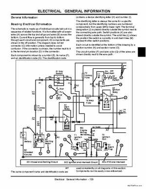
contains device identifying letter (H) and number (I)The identifying letter is always the same for specific component, but the identifying numbers are numbered consecutively from upper left to lower rightThe terminal designation (J) is placed directly outside the symbol next to the connecting wire pathSwitch positions (K) are also placed directly outside the symbolThe solid line (L) shows the position the switch is currently in and dash lines (M) represent other switch positionsEach circuit is identified at the bottom of the drawing by section number (N) and section name (O)The circuit number (P) and wire color (Q) of the wires are shown directly next to the wire path The schematic is made up of individual circuits laid out in sequence of related functionsIt is formatted with all power wires (A) across the top and all ground wires (B) across the bottomCurrent flow is generally from top to bottom through each circuit and componentAll components are shown in the off positionThe diagram does not list connector (C) information unless needed to avoid confusionIf the connector is shown, the number next to it is the terminal pin location (D) in the connectorEach component is shown by symbol (E), its name (F), and an identification code (G)The identification code