2006-2014 Honda FourTrax ATV TRX250 EX TRX250X Service Manual, Page 324Get this manual
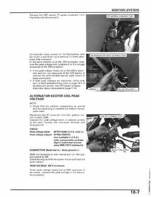
IGNITION SYSTEM Remove the CKP sensor 2P green connector from the frame and disconnect it
Connect the tester probes to the Blueyellow wire terminal (+) and Green wire terminal of the alternator side connectorIn the same manner as at the ICM connector, measure the peak voltage and compare it to the voltage measured at the ICM connector If the peak voltage measured at the ICM is abnormal and the one measured at the CKP sensor is normal, the wire harness has an open circuit or loose connection If both peak voltages are abnormal, check each item in the troubleshooting chart on page 18-4If all items are normal, the CKP sensor is faultyAlternator stator replacement (page 11-6)
ALTERNATOR EXCITER COIL PEAK VOLTAGE
Check that the cylinder compression is normal and the spa rk plug is installed correctly in the cyl inder headDisconnect the 2P connector from the ignition control module (lCM)Connect the peak voltage tester or adapter probes to the wire harness side connector terminal and body ground TOOLS: Peak voltage tester MTP07-0286 (U.S.Aonly) or Peak voltage adapter 07HGJ-0020100 (not available in U.S.A with commercially available digital multi meter (impedance 10MQDCV minimum) CONNECTION: Blackred (+)Body ground (-) Shift the transmission into neutral and turn the igni tion switch to ONCrank the engine with the starter motor and read the peak voltagePEAK VOLTAGE: 100 minimum If the peak voltage measured at ICM connector is abnormal, measure the peak voltage at the alternator connectorE u