2004 Bombardier Quest/Traxter Series Shop Manual, Page 373Get this manual
Section 06 ELECTRICAL Subsection 07 (HYDRAULICELECTRIC SHIFT SYSTEM)
Removal
Traxter Series except Traxter MAX Remove fuel tank coverRefer to BODYRemove seat pivot barTraxter Series Unplug STPSRemove screws and lock washers retaining STPS on enginePull STPS
VSS (Vehicle Speed Sensor)
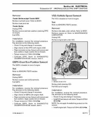
The VSS is located on front of engine
Refer to SENSORS TESTS section
Removal
Remove skid plate under vehicleRefer to BODYRemove engine oilRefer to MAINTENANCE LUBRICATIONUnplug VSSRemove engine bolt under VSS
Installation
For installation, reverse the removal procedurePay attention to the following details: Check O-ring and change if necessary Align interior of the STPS with engine shaft Place connector on topSecure with screws and lock washersApply Loctite 243 on threads Torque screws to Nm (18 lbfin) Calibrate STPSRefer to DIAGNOSTIC CALIBRATION MODE section, task 5
GBPS (Gear Box Position Sensor)
The GBPS is located on rear of engine