2004 Bombardier Quest/Traxter Series Shop Manual, Page 267Get this manual
Section 04 ENGINE TRAXTER Subsection 10 (CRANKSHAFTBALANCER SHAFT)
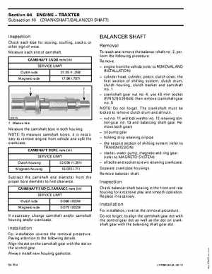
Inspection
Check each lobe for scoring, scuffing, cracks, or other sign of wearMeasure each end of camshaftCAMSHAFT ENDS mm (in) SERVICE LIMIT Clutch side Magneto side 31.95 (1.258) 17.96 (.707)
BALANCER SHAFT
Removal
To reach and remove the balancer shaft no2, perform the following procedureRemove: engine from the vehicle (refer to REMOVAL AND INSTALLATION) cylinder head, cylinder, piston, clutch cover, the first section of shifting system, clutch drum, clutch housing, clutch basket and camshaft no1 crankshaft gear nut no4, use 46 mm socket (PN 529 035 648), then remove crankshaft gear no5 NOTE: Do not forgetThe crankshaft must be locked to remove clutch drum and all nuts nut no11 and lock washer no12 retaining control gear no13 and balancing shaft gearRemove both gears oil pump gear holding strip retaining oil pipe the second section of shifting system (refer to TRANSMISSION) starter, water pump, magneto and ring gear (refer to MAGNETO SYSTEM) all bolts and socket screws retaining crankcaseSeparate crankcase housingsRemove balancer shaft