2004 Bombardier Quest/Traxter Series Shop Manual, Page 138Get this manual
Section 03 ENGINE QUEST Subsection 08 (CYLINDER AND CYLINDER HEAD)
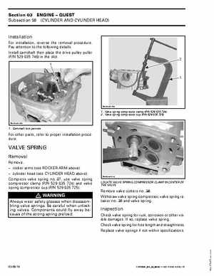
Installation
For installation, reverse the removal procedurePay attention to the following detailsInstall camshaft then place the drive pulley puller (PN 529 035 746) in the slot2
R610motr120A
1Valve spring compressor clamp (PN 529 035 724) 2Valve spring compressor cup (PN 529 035 725)
R610motr119A
1Camshaft lock position
For other parts, refer to proper installation procedure
VALVE SPRING