2004 Bombardier Outlander 330/400 Factory Service Manual, Page 197Get this manual
Section 03 ENGINE Subsection 12 (CVT)
Installation of Driven Pulley
For installation, reverse the removal procedurePay attention to the following detailsInstall sliding half no30 into fixed half no31Place O-ring no34 on main shaft splines and move it with spacer no35 in end positionCAUTION: Chamfer on inside diameter of the spacer must face engine side3 2
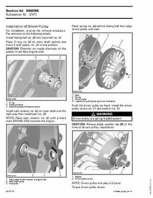
Place spring no33 behind sliding half then align driven pulley with cam1 3
R400motr192A
R400motr190A
1O-ring 2Distance sleeve 3Chamfered area of distance sleeve
Cam Spring Driven pulley Location for pushing during screw installation