2003 Bombardier Outlander 400 Factory Service Manual, Page 292Get this manual
Section 08 SUSPENSION Subsection 03 (RE AR SPE SIO N)
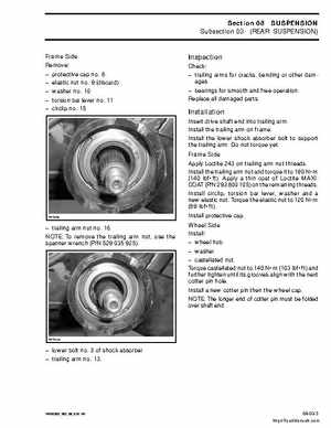
Fra Side Re move: protective cap no8 elastic nut no9 (discard) asher no10 torsion bar lever no11 circlip no15
Inspection
Check: trailing arms for cracks, bending or other damages bearings for smooth and fre operationReplace all damaged parts
Installation
Insert drive shaft end into trailing armInstall the trailing arm on fram eInstall the lo er shock absorber bolt to support the trailing armDo not torque yetFra Side Apply Loctite 243 on trailing arm nut threadsInstall the trailing arm nut and torque it to 190 Nm (140 lbfft)Apply thin coat of Loctite AXIC AT (PN 293 800 105) on the re maining threadsInstall circlip, torsion bar le er, ash er and ne elastic nutTorque the elastic nut to 120 Nm (89 lbfft)Install protective capW heel Side Install: he el hub asher castellated nutTorque castellated nut to 140 Nm (103 lbfft) and further tighten until its grooves align ith the next cotter pin holeInstall ne cotter pin then the he el capN OTE: The longer end of cotter pin must be folded over shaft end