2002 Bombardier Quest 650XT Service Manual, Page 245Get this manual
Section 07 STEERINGCONTROL SYSTEMS Subsection 02 (STEERINGCONTROL SYSTEMS)
HANDLEBAR
Removal
Remove: steering cover (refer to BODY) handlebar grips no1 brake handles no2(see below in this section) throttle handle no3 and multi-function switch no4 (see below in this section) steering clamp mounting bolts no5 and steering clamp no6 handlebar no7NOTE: On the XT model, remove the hand protector and windshieldRefer to BODY
Installation
For the installation, reverse the removal procedureInstall new cotter pinsBoth ends of cotter pin must be folded
Removal
Place the vehicle on jack stands and remove front wheel(s)Remove cotter pin no18, castellated nut no19, hardened washer no20 and flat washer no21
Inspection
Inspect ball joint ends for wear or looseness, if excessive, replace
Inspection
Inspect the handlebar for damage, cracks or bending, replace if any problems is detected
Installation
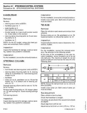
For the installation, reverse the removal procedurePay attention to the following detailsAt the time of the reinstallation or the new tierod(s) installation, screw threaded end of tie-rod into ball jointThe maximum length for tie-rod groove to ball joint end must be the value in the following chart: