2002 Bombardier Quest 650XT Service Manual, Page 224Get this manual
Section 06 DRIVE TRAIN Subsection 02 (FRONT DRIVE)
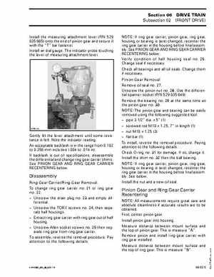
Install the measuring attachment lever (PN 529 035 665) onto the end of pinion gear and secure it with the "T" bar fastenerInstall an dial gaugeThe indicator probe touching the lever of measuring attachment lever
NOTE: If ring gear carrier, pinion gear, ring gear, housing or bearing is (are) changed, recenter the ring gear carrier in the housing before final assemblySee PINION GEAR AND RING GEAR CARRIER RECENTERING belowVerify condition of half housing seal no26Change seal if necessaryCheck all bearings and all oil sealsChange them if necessaryPinion Gear Removal Remove oil seal no27Unscrew the pinion nut no28Use the differential spanner socket (PN 529 035 649)Remove the bearing no29 at the same time as the pinion gear no30NOTE: The pinion gear and bearing can be easily removed using the following suggested tool: pipe 3-12" diax 5" (1) screwed rod M10 1.25, 7" in length (1) nut M10 1.25 (3) flat bar (1)To install, reverse the removal procedurePaying attention to the following detailsCheck O-ring no31 for damageIf so, change itInstall the shim no32 then the ball bearingNOTE: If ring gear carrier, pinion gear, ring gear, housing or bearing is (are) changed, recenter the ring gear carrier in the housing before final assemblySee belowInstall the nut and new oil seal