2002 Bombardier Quest 650XT Service Manual, Page 216Get this manual
Subsection 06
Section 05 ELECTRICAL (INSTRUMENTS AND ACCESSORIES)
Installation
For the installation, reverse the removal procedure
Installation
For the installation, reverse the removal procedure
XT Model
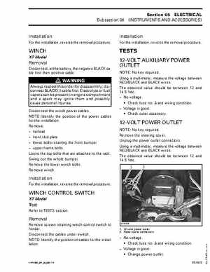
TESTS 12-VOLT AUXILIARY POWER OUTLET
NOTE: No key requiredUsing multimeter, measure the voltage between REDBLACK and BLACK wiresThe obtained value should be between 12 and 14.5 Vdc No voltage: Check fuse no3 and wiring condition Voltage is good: Check outer accessory
Removal
Disconnect, at the battery, the negative BLACK cable first then positive cable
WARNING
Always respect this order for disassembly; disconnect BLACK (-) cable firstElectrolyte or fuel vapors can be present in engine compartment and spark may ignite them and possibly cause personal injuriesDisconnect the winch power cablesNOTE: Identify the position of the power cables for the installationRemove: fairlead front skid plate lower bolts retaining the front bumper upper frame boltsLoose the top bolts that are attached to the rackSwing out the whole bumperRemove the lower winch boltsRemove winch